Using The Polar Wizard To Balance A Propeller
These images show how easy it is to balance a propeller with the help of the "Polar Wizard". The Polar Wizard is simply an electronic version of the venerable polar chart that has been used to balance propellers for many years.
The procedure is simple: having measured the vibration with no weight attached, you then attach a trial weight to the spinner and measure the vibration again - the Wizard now has enough information to calculate how the trial weight should be adjusted (amount and position) to make the balance good.
 Initial condition
This is the first reading captured, no weight has been attached to the spinner yet. The engine is a 6 cylinder Jabiru and the prop is an Airmaster.
The captured polar point is shown as a black circle and above it is shown the RPM at the time the point was captured along with the magnitude of the vibration (expressed as a velocity, in units of Inches Per Second or IPS) and the angle (in degrees, 0-359).
It's showing about 0.5 IPS of vibration which means that we need to attach a fair sized trial weight to make much difference. The angle is 315 degrees but we can ignore the angle for now.
Some engines have a starter ring on the front that has holes drilled in it which is perfect for attaching balance weights. Otherwise, the balance weight is normally attached to the outside of the spinner using using one of the existing spinner attachment holes and a longer than normal screw.
In this case, we attached the weight (4 x AN970-3 washers) to the outside of the spinner. Having carefully checked that the weight is secure and is not able to touch anything (like the cowling), another polar point can be captured.
Note that at this stage, the position of the weight is not important.
 Trial weight attached
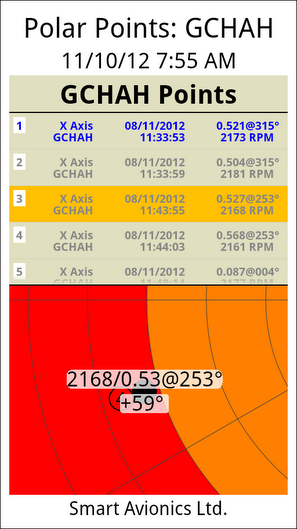
This is the reading after the trial weight has been attached to the spinner and the point has moved on the chart.
You can see that although the magnitude of the vibration has hardly changed, the angle has changed from 315 to 253. Furthermore, a "solution bubble" is now being shown that provides a succinct description of how the trial weight needs to be adjusted to make the balance good. In this case the Wizard is saying move the weight 59 degrees forward (in the direction of prop rotation). It's not suggesting that the amount of weight should be altered, just the position.
As the spinner only has 6 (equally spaced) screws for attaching it to the backplate, it is fortunate that the Wizard wants the weight moving by around 60 degrees as that's easily achieved by moving the weight to the next screw (in the direction of rotation).
It's more common for the weight needing to be moved to a position between the spinner screws in which case the weight has to be "split" with some of it being attached to the screw "before" the desired position and the remainder "after" the desired position.
 Weight moved forward
We moved the weight forward to the next spinner screw hole and this is the result.
As you can see, the point has moved close to the centre of the chart and the magnitude has reduced greatly to 0.09IPS so the job should soon be done.
The Wizard is now telling us that to improve the balance we need to move the weight back 8 degrees and increase it by a factor of 1.11 (that's about 10%).
Luckily the rim of the spinner backplate had another hole that was both in the right place (just about!) and accessible so we moved the weight to there. As this new position did not correspond to one of the spinner fixing screws, another screw and nut was required and they provided the extra weight that the Wizard was calling for.
 Final position
Several points were captured, the best being this one. The Vibration level is now down to 0.05IPS (that's 1/10 of the original magnitude) and no change in weight
or position is required.
To finish the job, the aircraft owner noted the final position of the weight, removed the spinner and securely reattached the weight in the same position on the inside of the spinner backplate's rim.
Most often, the weight is moved to the spinner backplate by drilling a hole in the backplate as close to the rim as possible and securely bolting the weight to the backplate. When this is done, the weight normally needs to be made larger to take into account the fact that the new position is at a smaller radius than it was before.
Copyright 2013-2014 Smart Avionics Ltd.